

 en
en ru
ru es
es ar
ar


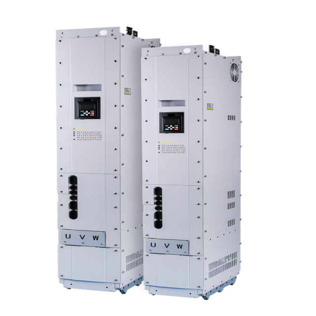


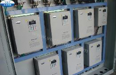
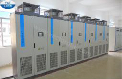
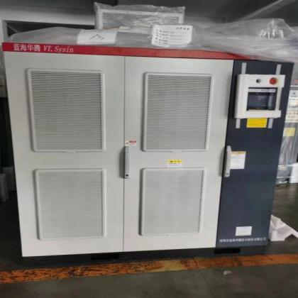
DTS800 series drive, driven by DTC control technology, is a multi-drive AC Inverter developed independently by V&T Company. With fast torque response performance and higher speed stability accuracy, DTC control can be realized with or without encoder. Even without encoder, the unique DTC control technology, with characteristics of large torque at low frequency and fast torque response, can meet application requirements in most cases.
Sample provide:
YESSample freight payer:
BuyerTerm of payment:
T/T, L/C, D/PCustomized:
YESWarranty:
18 MonthsDelivery Time:
5-7 Working Days For Standard Series; 7-14 Working Days For Customized AC DrivesTransportation:
Express · Sea Freight · Land Freight · Air FreightPackage:
Standard Export Package Carton/WoodAvailability:
OEM/ODM, Minmum Order RequestPlace of Origin:
ChinaShipping Port:
ShenzhenCertification:
CE, EAC, ISO9001, OHSAS18001, TS16949, SGSProduct Overview
| Item | Description |
| Product Name | Multi-Drive AC Inverter |
| Model Number | DTS800-H-4TxxG-AX-XX |
| Power Range | 75kW-500kW |
| Rated Input Voltage |
AC220V DC320V AC400V DC540V AC690V DC980V |
| Rated Output Voltage | 3 phase 0 to rated input voltage |
| Input Frequency | 50Hz/60Hz |
| Applicable Motor | Asynchronous Motor |
| Control Mode | Scalar Control, DTC Control Without Encoder, DTC Control With Encoder |
| Communication | Modbus 485 RTU, CANopen, Profibus-DP, CAN |
| IP Code | Standard IP20 |
| Overload Capacity | 150% 1 minute, 180% 10 seconds, 200% 0.5 second, interval: 10 minutes (inverse time lag feature) |
Features
1. Adopt the independently developed DTC control technology with stronger robustness and fast torque response.
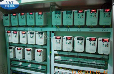
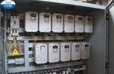
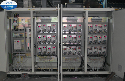
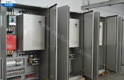
2. Adopt the common DC bus connection mode. Multi-Drive Inverter has the advantages of simple installation, convenient connection, reducing control cabinet space and saving energy consumption. This largely saves the wiring, installation and maintenance costs.
3. Built-in buffer circuit, no need for additional buffer circuit and directly powered by DC power supply.
4. Wide coverage of power levels, up to 3000kW in parallel voltage.
5. Wide voltage level coverage with three levels, respectively corresponding to 3AC220V, 3AC380V and 3AC690V for rectifier.
6. Full series of LCD operating panels by default (optional Chinese/English language).
7. Commission and monitor visa a browser without installing PC software and inserting rich built-in application macros.
8. Customized programming function, convenient commissioning and flexible application.
9. Support changing to active rectification unit.
Model Explanation

Product Catalogue
DTS800-H−4T□□□G DC540V Constant Torque/Heavy Load Application
Power (kW)
75
90
110
132
160
185
200
220
250
280
315
355
400
450
500
Motor power (kW)
75
90
110
132
160
185
200
220
250
280
315
355
400
450
500
Output
Voltage (V)
Three-phase 0 to rated input voltage
Rated Current (A)
150
176
210
253
304
350
380
426
470
520
600
650
690
775
860
Max Current (A)
270
317
378
455
547
630
684
765
846
936
1080
1170
1242
1395
1548
Overload capacity
150% 1 minute, 180% 10 seconds, 200% 0.5 second, interval: 10 minutes (inverse time lag feature)
Input
Rated Voltage
DC540V
Braking unit
Built-in as option
External braking unit
Protection class
IP20
Cooling mode
Forced air cooling
Note: 75kW~200kW: optional built-in brake unit.
If larger power is needed, the machine can be paralleled, with a maximum of 4 parallel machines, and the maximum power is 500*4=2000kW.
If lower power is needed, choose the VTS series single-drive product. And It supports AC input and DC input. For details, see introductions of the VTS series product or VTS30 series product.
Technical Specifications
|
Control characteristics |
Control Mode |
Scalar Control |
No-encoder DTC Control |
DTC Control With encoder |
|
Starting torque |
0.50Hz 150% |
0Hz 100%;0.25Hz 200% |
0.00Hz 200% |
|
|
Speed regulation range |
1:100 |
1:200 |
1:1000 |
|
|
Steady speed precision |
± 0.5% |
± 0.2% |
± 0.02% |
|
|
Torque control |
No |
Yes |
Yes |
|
|
Torque control precision |
— |
±5% |
±3% |
|
|
Torque response time |
— |
<20ms |
<10ms |
|
|
Product function |
Key function |
Under-voltage regulation, switchover of run command source(operation panel, terminal and communication), speed tracing function, torque limit, multi− step frequency reference, motor data identification, S curve acceleration and deceleration,Mechanical brake control, PID regulation, droop control, current limit, Torque/speed control mode switching, user load curve, master-slave control, user-defined programming, AFE rectifier feedback. |
||
|
Speed reference source |
Parameter setting, operation panel UP/DN, terminal, terminal UP/DN, communication, analog, more combinations. |
|||
|
Frequency range |
0.00~600.00Hz |
|||
|
Starting mode |
Automatic startup, speed tracking startup, automatic DC excitation startup, constant time DC excitation startup |
|||
|
Acceleration time and deceleration time |
Multiple acceleration and deceleration times, and S-curve acceleration and deceleration modes can be set |
|||
|
Dynamic braking |
With overload capacity estimation |
|||
|
DC braking |
DC braking function does not required waiting time to start to realize quick braking |
|||
|
Magnetic flux braking |
Activate and cancel options, and do not act when decelerating by default |
|||
|
Unique functions |
Keypad |
Standard LCD operation panel |
||
|
Browser adjusting |
No special upper computer monitoring software is required, and you can directly use the browser to adjust on the computer |
|||
|
Multi IO terminal |
Up to 13 digital inputs and 6 relay outputs |
|||
|
Multiple parameters display modes |
User parameters, monitoring parameters, non factory value parameters |
|||
|
Parameters copy |
The standard operation panel can realize the parameters upload, download |
|||
|
Dual 485 communication ports |
Dual 485 communication ports support Modbus protocol (RTU). The maximum distance is 500 meters |
|||
|
Common DC bus |
All series product support common DC bus |
|||
|
Independent duct |
All series product adopts independent duct design and supports the installation of heat-sink outside the cabinet |
|||
|
Power-On-Self-Test (POST) |
Realizing the POST of internal and peripheral circuits, including motor grounded, abnormal +10V power supply output, analog input and disconnection, etc. |
|||
|
user-defined programming |
It does not need a computer, and can realize the user-defined programming function, and can encrypt the user-defined programming |
|||
|
AFE active rectifier |
Rectification feedback function can be realized |
|||
|
Protection function |
Power supply under-voltage, over-current protection, over-voltage protection, interference protection, abnormal comparison level, motor data identification failure, module(IPM) protection, heat-sink over temperature protection, inverter overload protection, motor overload protection, peripheral protection, abnormal current detection, output short circuit to ground, interruption of power supply when in running status, abnormal input power, output phase loss, abnormal EEPROM protection, abnormal pre-charging contactor detection, temperature sampling disconnection, encoder disconnection, abnormal analog input, motor over temperature protection(PTC), abnormal communication, hardware overload protection, over-speed protection and other protection functions. |
|||
|
Efficiency |
At rated power: 75kW and above power class ≥98% |
|||
|
Environment |
Operating site |
The product should be mounted vertically in the electric control cabinet with good ventilation. Horizontal or other installation modes are not allowed. The cooling medium is the air. The product should be installed in the environment without dust, corrosive gas, combustible gas, oil mist, steam, drip and free from direct sunlight |
||
|
Ambient temperature |
−10 to +40ºC, the product must be de-rated rated output current for the ambient temperature between 40ºC to 50ºC, the rated output current must be de-rated for 1% per 1ºC temperature rise |
|||
|
Humidity |
5 to 95%, no condensing |
|||
|
Altitude |
0 to 2000m, the product must be de-rated rated output current for the altitude above 1000 meters, the rated output current must be de-rated for 1% per 100 meters rise |
|||
|
Vibration |
3.5 m/s2,2~9Hz;10 m/s2,9~200Hz;15 m/s2,200~500Hz |
|||
|
Storage temperature |
-40~+70℃ |
|||
Functions of Control Circuit Terminals
| Type | Terminal | Description | Technical specification |
| Modbus/CAN | BUS+ | RS485+ /CANH | Modbus:Rate: 4800/9600/19200/38400/57600bps |
| Up to 32 sets of equipment can be paralleled. Relay shall be used if the number exceeds 32 | |||
| Maximum distance: 500m | |||
| CAN:Max rate 1Mbps | |||
| BUS− | RS485− /CANL | Select 485 or CAN communication by jumper | |
| GND | Modbus/CAN Communication Ground | Internal isolated with COM | |
| Operation pane Modbus | CN11 | RS485 port of operation panel | The upper computer communication connection is the same as the terminal 485 |
| The maximum distance between the operation panel and the operation panel interface is 15 meters (standard twisted shielded network cable) | |||
| Digital input | +24V | +24V |
24V±10%, internal isolated with GND Maximum output current: 200mA, with overload and short circuit protection |
| PLC | Power supply of multi−function input terminal | Short circuited with +24V by default | |
| X1~X13 | Multi−function input terminals 1 ~ 13 | Input specification: 24VDC,5mA | |
| Frequency range: 0 ~ 200Hz | |||
| Voltage range: 24V±20% | |||
| COM | Ground terminal for +24V | Internal isolated with GND | |
| Relay output | RA1/RB1/RC1 | Relay output | RA1−RB1:normally closed |
| RA1−RC1:normally open | |||
| Contact capacity:250VAC/1A,30VDC/1A | |||
| RA2/RB2/RC2 | Relay output | RA2−RB2:normally closed | |
| RA2−RC2:normally open | |||
| Contact capacity:250VAC/1A,30VDC/1A | |||
| RA3/RC3 | Relay output | RA3−RC3:normally open | |
| Contact capacity:250VAC/1A,30VDC/1A | |||
| RA4/RB4/RC4 | Relay output | RA1−RB1:normally closed | |
| RA1−RC1:normally open | |||
| Contact capacity:250VAC/1A,30VDC/1A | |||
| RA5/RB5/RC5 | Relay output | RA2−RB2:normally closed | |
| RA2−RC2:normally open | |||
| Contact capacity:250VAC/1A,30VDC/1A | |||
| RA6/RC6 | Relay output | RA3−RC3:normally open | |
| Contact capacity:250VAC/1A,30VDC/1A | |||
| Analog input | +10V | Analog input reference voltage | 10V ±3%,Internal isolated with COM |
| Maximum output current: 10mA, with short circuit and overload protection | |||
| AI1 | Analog input channel 1 | -10V~10V,input impedance 20kΩ,Resolution: 12 bits(0.025%) | |
| AI2~AI5 | Analog input channel 2~5 | 0~20mA:input impedance 500Ω | |
| GND | Analog ground terminal | Internal isolated with COM | |
| Analog output | AO1 | Analog output 1 | 0~20mA:allowable output impedance 200~500Ω |
| 0~10V :allowable output impedance ≥10kΩ,Output precision 2%,Resolution: 10 bits(0.1%) with short circuit protection | |||
| 0 ~ 20mA or 0 ~ 10V output can be selected by jumper | |||
| AO2 | Analog output 2 | Same AO1 | |
| GND | Analog ground terminal | Internal isolated with COM |
Note: * If the user can adjust the potentiometer indirectly at+10V and GND, the resistance of the potentiometer should not be less than 5k Ω.
Terminal Wiring


Installation Dimension


Installation Dimension
|
Voltage |
Model |
Outline and mounting dimension (mm) |
weight (kg) |
||||||
|
W |
H |
D |
W1 |
H1 |
T1 |
⌀d |
|||
|
AC 400V
DC 540V |
DTS800−H−4D75G |
199 |
800 |
448 |
− |
620 |
7.5 |
− |
− |
|
DTS800−H−4D90G |
|||||||||
|
DTS800−H−4D110G |
|||||||||
|
DTS800−H−4D132G |
199 |
959.5 |
520.5 |
− |
768 |
7.5 |
− |
− |
|
|
DTS800−H−4D160G |
|||||||||
|
DTS800−H−4D185G |
|||||||||
|
DTS800−H−4D200G |
|||||||||
|
DTS800−H−4D220G |
247 |
1485 |
459.5 |
− |
1414.5 |
− |
− |
− |
|
|
DTS800−H−4D250G |
|||||||||
|
DTS800−H−4D280G |
|||||||||
|
DTS800−H−4D315G |
|||||||||
|
DTS800−H−4D355G |
260 |
1585 |
576.5 |
160 |
1516.5 |
− |
− |
− |
|
|
DTS800−H−4D400G |
|||||||||
|
DTS800−H−4D450G |
|||||||||
|
DTS800−H−4D500G |
|||||||||
Optional Accessories/Expansion Card
|
Item |
Name |
Model |
Function Explanation |
|
Operation panel Pallet |
Pallet |
VTS−DP05 |
Mounting accessories of operation panel |
|
Extensible Card |
PG Feedback Card |
EX−PG01 |
Power supply +12~24V, open collector, push pull type encoder feedback card, maximum current 200mA, up to 80K pulse input. |
|
EX−PG03 |
Power supply +12~24V, open collector, push pull type encoder feedback card, maximum current 200mA, up to 80K pulse input, with frequency division output. |
||
|
EX−PG20 |
Power supply +12~24V, open collector, push pull type encoder feedback card, maximum current 200mA,up to 80K pulse input,with two relays output. |
||
|
EX−PG02 |
Power supply +5V, differential type encoder feedback card, maximum current 150mA, up to 300K pulse input. |
||
|
EX−PG04 |
Power supply +5V, differential type encoder feedback card, maximum current 150mA, up to 300K pulse input, with frequency division output. |
||
|
EX−PG21 |
Power supply +5V, differential type encoder feedback card, maximum current 150mA, up to 300K pulse input, with two relays output. |
||
|
Relay extensible card |
EX−PG22 |
two relays output. |
|
|
Communication module of CANopen slave station |
EX−CA04 |
CANopen DS301、DS303、DS305 protocol Installation method: internal and external |
|
|
Profibus−DP communication adapter card |
EX−CA06 |
Installation method: internal and external |
|
|
communication adapter card |
EX−CA13 |
ProfiNet Industrial Ethernet communication, with 5V incremental encoder interface and frequency division output. Installation method: Internal |
|
|
Keypad extension cable |
2 meters keypad extension cable |
CB1−200 |
2 meters keypad extension cable |
|
3 meters keypad extension cable |
CB1−300 |
3 meters keypad extension cable |
Applications
 |
 |
 |
 |
 |
 |
 |
 |
|
DTC Control Drive Inverter Representative Industry
It is suitable for motor-driven applications in all walks of life, including 690V AC Drive, DC 540V Input Inverter, fans, water pumps, lifting equipment, printing equipment, paper-making equipment, belt conveyor, etc. especially for applications in process industries such as the pulp, metals, mining, cement, power, chemical, and oil & gas industries.
If you are interested in our products and want to know more details,please leave a message here,we will reply you as soon as we can.
Categories
The high-voltage variable frequency drive (VFD) system is designed with high reliability, ease of operation, and high performance as its core objectives. Utilizing advanced IGBT power devices, the system incorporates fully digital control through a combination of DSP, FPGA , and ARM micro controllers.

V9-R is a special-purposed drive control unit for Compressor Controller with V/F vector control functions. It devotes to controlling water-source heat pump, air-source heat pump systems and air conditioning control system. It not only achieves requirements of cost saving, improvement on product quality and production efficiency,but also easy maintenance and easy commissioning.

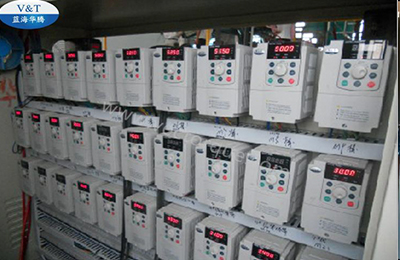
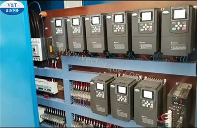
As the VFD manufacturer in china, V&T has rich experience in electric drive fields. V&T V6-H series is a high performance vector control and torque control AC inverter.The product adopts close-loop vector control technology and torque control technology which are synchronized with the current international advanced technology, and it has the same excellent control performance with the international high-end frequency drive.

As the VFD manufacturer in china, V&T has rich experience in electric drive fields. V&T V9−H Series General Purpose Inverter is a high-performance vector control and torque controlled frequency drive. Vector control technology and torque control technology are employed. It can better meet the needs of various transmission applications.Voltage range covers 200V, 400V, 690V, and 1140V. The product power range covers 0.4kW to 3MW.

Full Range Product ■ Covers the MCU six-in-one integrated controller, MCU five-in-one integrated controller, MCU / auxiliary drive four-in-one integrated controller, MCU / auxiliary drive three-in-one integrated controller, hybrid two-in-one integrated controller, auxiliary drive two-in-one integrated controller, motor + MCU integrated system, motor + gearbox + MCU integrated system ■ Designed to meet customer needs for customized design ■ Adapted for permanent magnet synchronous motor (PMSM), asynchronous motor, etc. ■ Power range covers from 3kW to 355kW.

As the VFD manufacturer in china, V&T has rich experience in electric drive fields. V&T V5-H series is a high-performance vector control inverter. The product adopts open-loop vector control technology ;which is completely synchronized with the most advanced technology in the world. It has the excellent control performance with the international high-end frequency drive.

As the VFD manufacturer in china, V&T has rich experience in electric drive fields. Adopting brand-new vector control technology, VTS series inverter can be compatible with the control of synchronous motor, asynchronous motor and reluctance motor, as well as the encoders with multiple specification and abundant communication interface and support English liquid crystal display, five-digit digital pipe display operation panel; and with the protection functions of usability, extendability, small volume, light weight and perfection, VTS series AC drive can meet the medium-high application demands.

Elevator Main Control Board AIEC-MCB-A
 3-8th Floor, Tower 2, Zhiyan lnnovation Building, Yutang Street, Tianliao Community, Guangming District, Shenzhen, Guangdong Province, China.
 Ms. Nina


If you are interested in our products and want to know more details,please leave a message here,we will reply you as soon as we can.


