en
en ru
ru es
es ar
ar


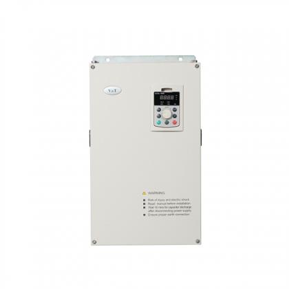
Integrated Elevator Control Cabinet
Sample provide:
YESSample freight payer:
BuyerTerm of payment:
T/T, L/C, D/PCustomized:
YESWarranty:
18 MonthsDelivery Time:
5-7 Working Days For Standard Series; 7-14 Working Days For Customized AC DrivesTransportation:
Express · Sea Freight · Land Freight · Air FreightPackage:
Standard Export Package Carton/WoodAvailability:
OEM/ODM, Minmum Order RequestPlace of Origin:
ChinaShipping Port:
ShenzhenCertification:
CE, EAC, ISO9001, OHSAS18001, TS16949, SGS
Product Overview
| Item | Description |
| Product Name | Integrated Elevator Inverter / Elevator AC Drive |
| Model Number | AIEC3300−C−40xxx |
| Power Range | 2.2kW-75kW |
| Rated Input Voltage | 3 phase 380V/480V |
| Rated Output Voltage | 3 phase 0 to rated input voltage |
| Input Frequency | 50Hz/60Hz |
| Applicable Motor | Asynchronous Motor, Synchronous Motor |
| Control Mode | Closed loop vector control with PG card |
| Communication | Modbus 485 RTU, CAN |
| IP Class | Standard IP20 |
| Overload Capacity | 150% 1 minute, 180% 10 seconds, 200% 0.5 second, interval: 10 minutes (inverse time lag feature) |
Model Explanation

Integrated Elevator Control Cabinet Feature:
● The hardware resources are fully integrated, the structure is simple, the volume is smaller, and the control cabinet is lighter;
● Modular structure, saving workers wiring time, easy to assemble, repair and replace;
● The internal interface board is designed for on-site installation, and the hoistway cable and the accompanying cable are directly connected to each other, avoiding trouble and wiring errors;
● Built-in over-voltage protection module, the input power supply is cut off in time when the local zero line is disconnected, and other modules of the system will not be damaged due to over-voltage;
● Built-in brake power supply board, direct output DC to control the brake. Control efficiency is improved. No high frequency clutter, the brake generates less heat and the brake noise is lower;
● The built-in DC24V switching power supply can directly supply power to the LOP, control panel board and other peripheral boards, and the rated output current can reach 5A;
● V&T Elevator Drive can match elevator internet monitoring module. It supports community monitoring and remote monitoring
Technical Specifications
|
Basic features |
Standard floor |
40 floors |
|
Elevator running speed |
≤ 4.00m/s |
|
|
Number of elevators in parallel/group mode |
≤ 4 sets |
|
|
Communication mode |
CAN /RS485/RS232 |
|
|
Control features |
Motor control mode |
Closed loop vector control with PG card |
|
Startup torque |
Up to 200% (depending on load) |
|
|
Speed range |
1:1000(Closed loop vector control with PG card) |
|
|
Speed control precision |
±0.05% (Closed loop vector control with PG card, 25±10℃) |
|
|
Torque limit |
200% of the rated torque |
|
|
Torque precision |
±5% |
|
|
No−load startup compensation |
When the elevator load is unknown, the system compensates the appropriate torque for the motor according to the running direction of the elevator, so as to make it start smoothly, minimize the car sliding at the moment of starting, and increase the comfort of elevator starting. |
|
|
Carrier frequency |
2~16kHz |
|
|
Product functions |
Key functions |
See product introduction for details |
|
Frequency range |
0~99Hz |
|
|
Acceleration/ deceleration time |
0.1~8s |
|
|
150% |
||
|
Special functions |
Protecting anti−plug |
Perfect protection circuit design, any wrong insertion will not damage, and will not affect other controller. |
|
Unique communication anti−interference |
In order to improve the anti−interference performance, the car top board and the main control board use the enhanced CAN communication technology, without shielding wire. |
|
|
Energy saving operation of standby power supply |
When the normal power supply is interrupted and the emergency power supply is used, the system reduces the running speed of the elevator in the prerequisite of guaranteeing the smooth running curve and stop at the nearest floor.Open the door first, close door after delay for a period of time, press any key in the car to open the door. |
|
|
Troubleshooting based on fault level |
Faults are classified into different levels based on the severity. Different levels of faults are rectified using different methods, improving the system operation efficiency. |
|
|
Auto−leveling |
The system implements automatic accurate leveling based on the floor pulse counting and up/down leveling feedback signals. |
|
|
Door pre−open function |
In automatic running state, when the elevator speed is smaller than 0.25 m/s and the door zone signal is active, the system shorts the door lock by means of the shorting door lock circuit relay and outputs the door open signal, implementing door pre−open. This improves the elevator use efficiency. |
|
|
Micro−leveling |
After landing at a floor, the elevator may move upward or downward due to the load change and the car door is not aligned with the ground, which is inconvenient for passengers and goods in and out. In this case, the system allows the elevator to run to the leveling position in the door open state at the re−leveling speed. |
|
|
Protection function |
Motor over−load protection, controller over−load protection, short circuit protection, input lost ;phase protection, output lost phase protection, over−voltage protection, under voltage protection, instantaneous power failure compensation, heatsink overheating, stall prevention, pulse encoder failure, brake unit protection, module protection, current sensor protection, speed abnormality protection, output short to ground protection, output imbalance protection, braking ;resistor short circuit protection, speed abnormality protection, running time limiter protection, level switch fault protection, EEPROM abnormal. |
|
|
PG card |
PG card type |
Support push−pull, open collector and SIN/COS encoder. |
|
I/O signal |
Optocoupler input control power supply |
Isolation 24 VDC |
|
Low voltage optocoupler isolation input |
24 x digital inputs. Optocoupler control signals are isolation 24 VDC power input signals. |
|
|
Low voltage optocoupler isolation input |
4 x digital outputs |
|
|
Relay output |
6 normally open contacts, single−pole single−throw, 5 A contact switchover capability. Contact load (Resistive): 5A250VAC or 5A28VDC |
|
|
USB interface |
Commissioning by cell phone, IoT monitoring |
|
|
CAN communication interface |
2 communication ports (Car top communication, parallel or group control) |
|
|
MODBUS communication |
2 communication ports (Outbound communication, Internet of Things) |
|
|
Analog input port |
1 single−ended or differential input, input voltage range −10 V to +10 V, precision 0.1% |
|
|
Operation and display |
Operation panel、Keypad、Mobile phone commissioning |
|
|
Environment |
Operating site |
The product shall be mounted vertically in the electric control cabinet with good ventilation. Horizontal or other installation modes are not allowed. The cooling media is the air. The product shall be installed in the environment free from direct sunlight, dust, corrosive gas, combustible gas, oil mist, steam and drip. |
|
Ambient temperature |
−10 ~ +40ºC, derated at 40 ~ 50ºC, the rated output current shall be decreased by 1% for every temperature rise of 1ºC |
|
|
Humidity |
5 ~ 95%, no condensing |
|
|
Altitude |
0 ~ 2000m, derated above 1000m, the rated output current shall be decreased by 1% for every rise of 100m |
|
|
Vibration |
Less than 5.9 m/s 2 (0.6 g) |
|
|
IP level |
IP20 |
|
|
Power distribution system |
TN/TT |
|
|
Pollution degree |
PD2 |
|
|
Storage temperature |
−20~+60℃ |
|
Braking Resistor Selection Guidance
|
Controller Model |
Braking unit |
Braking resistor |
|||
|
Power |
Resistance (Ω) |
Minimum resistance( Ω) |
Qty |
||
|
Single-phase 220V ,Range 220~240V |
|||||
|
AIEC3300−C−4005-220 |
Built-in as standard
|
300 |
140.0 |
125.0 |
|
|
AIEC3300−C−4007-220 |
600 |
71.0 |
64.0 |
|
|
|
AIEC3300−C−4011-220 |
1100 |
43.0 |
37.0 |
|
|
|
AIEC3300−C−4015-220 |
1200 |
40.0 |
35.0 |
|
|
|
AIEC3300−C−4018-220 |
1600 |
29.0 |
25.0 |
|
|
|
Three -phase 220V ,Range 220~240V |
|||||
|
AIEC3300−C−4005-220 |
Built-in as standard
|
600 |
72.0 |
66.0 |
|
|
AIEC3300−C−4007-220 |
1200 |
40.0 |
35.5 |
|
|
|
AIEC3300−C−4011-220 |
1600 |
29.0 |
25.0 |
|
|
|
AIEC3300−C−4015-220 |
2500 |
25.0 |
22.0 |
|
|
|
AIEC3300−C−4018-220 |
3500 |
14.5 |
13.0 |
|
|
|
AIEC3300−C−4022-220 |
4500 |
13.0 |
12.5 |
|
|
|
AIEC3300−C−4030-220 |
5500 |
12.5 |
12.0 |
|
|
|
AIEC3300−C−4037-220 |
6500 |
7.5 |
6.0 |
|
|
|
AIEC3300−C−4045-220 |
Built-in as optional
|
9000 |
5.5 |
4.5 |
|
|
AIEC3300−C−4055-220 |
11000 |
4.5×2 |
3.5×2 |
|
|
|
Three -phase 380V ,Range 380~440V |
|||||
|
AIEC3300−C−4002 |
Built-in as standard
|
600 |
295.0 |
230.0 |
|
|
AIEC3300−C−4003 |
1100 |
172.0 |
138.0 |
|
|
|
AIEC3300−C−4005 |
1600 |
116.0 |
90.0 |
|
|
|
AIEC3300−C−4007 |
2500 |
85.0 |
65.0 |
|
|
|
AIEC3300−C−4011 |
3500 |
55.0 |
42.0 |
|
|
|
AIEC3300−C−4015 |
4500 |
45.0 |
35.0 |
|
|
|
AIEC3300−C−4018 |
5500 |
35.0 |
25.0 |
|
|
|
AIEC3300−C−4022 |
6500 |
25.0 |
22.0 |
|
|
|
AIEC3300−C−4030 |
9000 |
20.0 |
15.0 |
|
|
|
AIEC3300−C−4037 |
11000 |
16.5 |
13.5 |
|
|
|
AIEC3300−C−4045 |
Built-in as option
|
13500 |
14.5 |
11.0 |
|
|
AIEC3300−C−4055 |
16500 |
12.0 |
10.0 |
|
|
|
AIEC3300−C−4075 |
12000×2 |
16.0×2 |
13.0×2 |
|
|
Motor Wiring
● It is forbidden to short circuit or ground the Elevator Drive Controller output terminal, otherwise the internal components of the integrated controller will be damaged.
● Do not short circuit the output cable and the integrated controller enclosure, otherwise electric shock may happen.
● It is forbidden to connect the output terminal of the integrated controller to the capacitor or LC/RC noise filter with phase lead, otherwise, the internal components of the integrated controller may be damaged.
● When contactor is installed between the integrated controller and motor, it is forbidden to switch on/off the contactor when the integrated controller is running; otherwise, large current will flow into the integrated controller, triggering the integrated controller protection action.
● Length of cable between the integrated controller and motor:
If the cable between the integrated controller and the motor is too long, the high−order harmonic leakage current of the output end will cause adverse impact on the integrated controller and the peripheral devices. Output AC reactor should be installed the motor cable is longer than 100m, Refer to the following table for the carrier frequency setting.
|
Length of cable between the integrated controller and motor |
Less than 50m |
Less than 100 m |
More than 100m |
|
Carrier frequency ( F0−07) |
Less than 15kHz |
Less than 10kHz |
Less than 5kHz |
Control Circuit Terminals
|
Type |
Terminal |
Description |
|
Keypad 485 |
CN12 |
RS485 port of keypad |
|
Terminal communication |
24V |
24V power supply for the board |
|
COM |
||
|
MOD+ |
Standard isolation RS−485,modbus communication for hall call and display |
|
|
MOD− |
||
|
CAN+ |
CAN communication, connect with car top board, machine−room−less monitoring board and DI/DO expansion board |
|
|
CAN− |
||
|
Digital input |
X1~X24 |
Input voltage range: 10Vdc~30Vdc Input resistance:4.7kΩ, current limit 5mA The function of digital input is setting by parameters of F5−01 to F5−24 |
|
COM |
Digital input common end |
|
|
X25~X28 |
High voltage input, input voltage: 110VAC ±15%,110VDC ±20% Safety circuit feedback and door lock feedback. |
|
|
Analog input |
AI |
Differential input, input voltage range −10 V to +10 V, it is used for load−cell |
|
Relay output |
Y1/M1~ Y6/M6 |
Relay output terminal NO: 5A/250Vac The relay output function is setting by parameters of F5−26 to F5−31 |
|
Group control |
CAN2+ |
CAN2 communication interface, for group or parallel/group control |
|
CAN2− |
||
|
COM |
||
|
IoT communication |
CN8 |
IoT communication interface |
Applications:
 |
 |
 |
 |
 |
 |
 |
 |
 |
Elevator Inverter Cabinet Representative Industry
As an advanced Integrated elevator drive solution provider and Elevator Inverter Manufacturer in China, The integrated elevator inverter of Shenzhen V&T Technologies Co.,Ltd. is suitable for Passenger Elevator, Cargo Lifting, Commercial Escalator, Villa elevator, Construction elevator ect.
If you are interested in our products and want to know more details,please leave a message here,we will reply you as soon as we can.
Categories
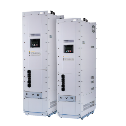
AIEC3300 series elevator controller support multiple motor control modes and encoder types, integrate advanced communication protocol, greatly improve the efficiency of elevator operation. support parallel/group control and provides multiple scheduling algorithms to meet the different requirements for customers.
Meet various vehicles applications By the end of June 2018, more than 200,000 units/sets have been used in various vehicle types; ■ Passenger vehicle (bus/commuter): small sea lion, Coster, 8.5m-12m passenger bus, 18m dual source trolleybus ■ Trucks: mini van and mini truck under 2.5 tons, 3.5-7.5 tons light trucks, 18-55 tons heavy trucks ■ Special-Purposed vehicles: sanitation truck, sprinkler truck, dust suppression truck, dock tractor, tunnel engineering tractor ■ Passenger car: A-class sedan, SUV
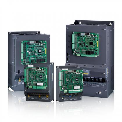
As the Variable Speed Drives manufacturer in china, V&T has rich experience in electric drive fields. V&T E5-H series is a high performance universal vector control inverter with superior performance-price ratio and powerful control functions. It is widely used in various drive and speed regulation in the fields of machine tools, food, paper making, metallurgy, chemical industry, wire and cable, power, textile and transmission.
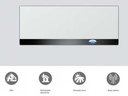
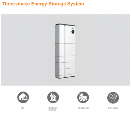
6.144KWH LiFePO4 Battery-BYD blade cell

Human Machine Interface
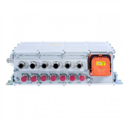
Long-term cooperation with many well-known vehicle manufacturers and system integrator ■ With more than ten years of technology accumulation and rich experience, we have thousands of successful industry applications; we can share our experience with partners; ■ We provide the customized product and customized design to achieve the best match between motor, motor controller and vehicle control system; ■ Enjoy high trust from customers and industry reputation.
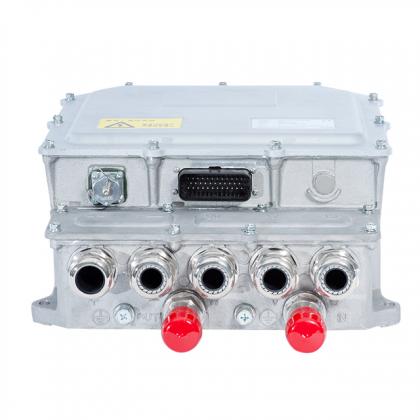
DTS800 series drive, driven by DTC control technology, is a multi-drive AC Inverter developed independently by V&T Company. With fast torque response performance and higher speed stability accuracy, DTC control can be realized with or without encoder. Even without encoder, the unique DTC control technology, with characteristics of large torque at low frequency and fast torque response, can meet application requirements in most cases.
 3-8th Floor, Tower 2, Zhiyan lnnovation Building, Yutang Street, Tianliao Community, Guangming District, Shenzhen, Guangdong Province, China.
 Ms. Nina


If you are interested in our products and want to know more details,please leave a message here,we will reply you as soon as we can.
Copyright © 2024 Shenzhen V&T Technologies Co.,Ltd.. All Rights Reserved. Power by

IPv6 network supported